
Module hotspots
Localised or broader temperature rises that differ from comparable modules.
Drone-based thermal and visual inspection for rooftop and ground-mounted PV systems, reviewed from an electrical engineering and asset-performance perspective.
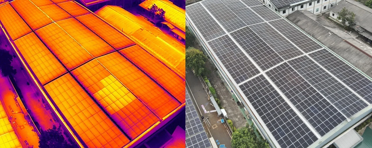
Infrared thermography makes temperature differences visible while the PV system is operating. ThermoSky reviews those patterns together with visual evidence, asset layout and available operating information.
Important interpretation note: A thermal anomaly is not automatically a confirmed defect. Weather, loading, angle, reflection, shading, soiling and system configuration can influence thermal appearance. Findings may require electrical testing or close physical inspection.
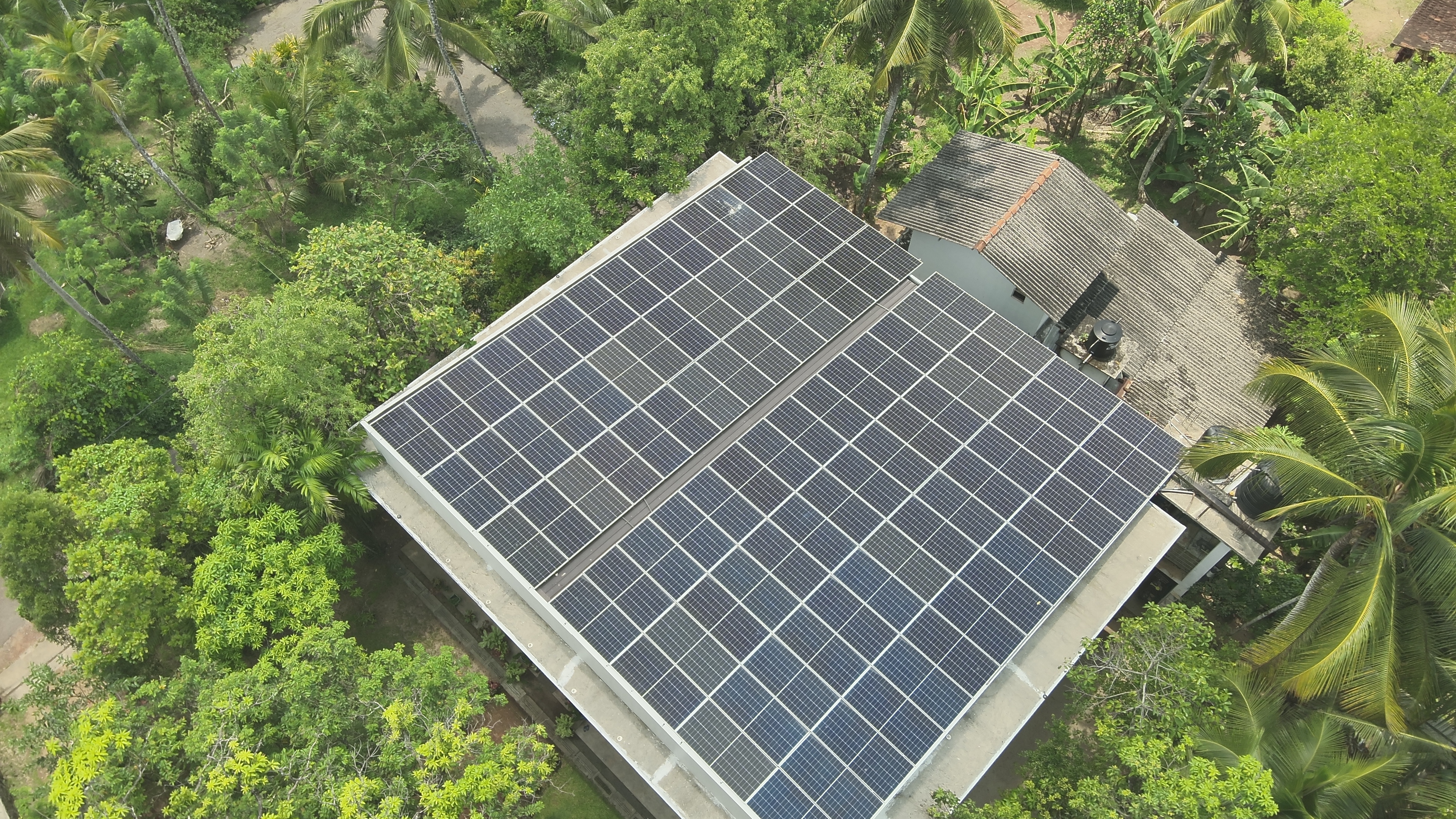
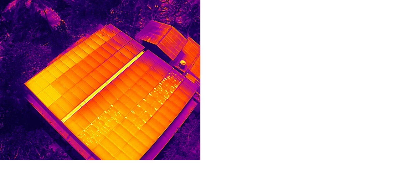
Using matched thermal and RGB imagery helps distinguish a temperature observation from a visible condition issue and provides clearer evidence for maintenance teams.
The achievable findings depend on the system design, operating condition, site access, weather, sensor capability and agreed inspection scope.
Localised or broader temperature rises that differ from comparable modules.
Patterns that may indicate inactive cells, cell strings or current-flow differences.
Thermal signatures that may justify investigation of diode or substring operation.
Temperature differences around the rear junction-box area or cable interface.
Abnormal heating patterns at accessible electrical connections or interfaces.
Visible and thermal evidence associated with obstruction, deposits or uneven exposure.
Module groups or areas whose behaviour differs from expected neighbouring assets.
Damage, displacement, contamination or other concerns apparent in high-resolution imagery.
.jpg)
The mission plan and deliverables are adapted to the physical layout, access constraints, inspection objective and asset records available.
Support for difficult-to-access arrays, maintenance investigations and periodic condition review.
Efficient coverage of larger module fields, with geotagged observations and inspection maps where applicable.
Focused review of areas identified through monitoring data, alarms, generation concerns or earlier maintenance records.
Periodic thermal and visual data collection to support preventive-maintenance programmes.
Thermographic inspections are planned around the objective and recognised limitations. Final timing is confirmed after reviewing the system and site.
Meaningful solar loadingThermal differences are easier to interpret when the array is generating under suitable irradiance.
Suitable environmental conditionsWind, cloud movement, recent rain and rapid weather changes can affect temperature patterns.
Appropriate view and distanceFlight height, angle, reflection and image detail are considered during mission planning.
Useful asset informationLayouts, module references, monitoring data and maintenance records can improve interpretation.
Report content is agreed before the inspection and may include the following, where feasible and relevant to the scope.
Overview of inspection conditions, limitations and key findings.
Thermal images, temperature observations and comparison with nearby assets.
High-resolution imagery and annotations supporting the observation.
Geotagged position, row or module reference where identification is possible.
An engineering priority to help organise review and follow-up.
Practical next steps, including where confirmation testing may be needed.
Share the system location, capacity, layout and the concern you want to investigate. ThermoSky will help define an appropriate inspection scope.